Composing Pixels - AGSL Shaders Compose
Take your Jetpack Compose UI to the next level with real-time pixel manipulation using shaders! Learn how AGSL lets you write GPU-powered visuals in Android 13+ with a clear step-by-step shader conversion from SKSL to AGSL.


Beginning with Android 13, the Android world was introduced to easy, concise way to implement shaders to your Jetpack Compose app. Let's dive in on how you can compose your pixels and elevate your user experience, starting with:
Taking pixel perfect to literal level!
Table Of Contents
- What are shaders?
- AGSL
- When should you not?
- Your Translator
- Composing Pixels
- Conclusion
What are Shaders?
Shaders, in simpler words is "a" piece of code that runs directly on your GPU, which is designed to efficiently execute mathematical calculations. A computer of any sort consists of 2 processing units, namely the CPU & GPU, and both of them are meant to perform very specific tasks. The CPU, also known as brain of the computer, is designed to perform multiple tasks in foreground or background.

Meanwhile the GPU usually loaded with a lot more cores is designed to perform the given task with all its might generally requiring dedicated memory called the VRAM.
You can learn more CPU vs GPU here.
Now there are various shaders such as Vertex, Geometry, Mesh shaders and so on. The Android view system uses something called Fragment/Pixel Shader. Fragment shaders are basically the same as pixel shaders except that fragments are pieces of geometry that actually end on the screen rather than pixel shaders that run on every pixel. Fragments shaders are small programs that run on every fragment to calculate whether it should be rendered.
The world of shaders offers a variety of shading languages such as HLSL for DirectX, MetalSL or MetalGLSL for Mac and iOS devices and now AGSL for Android devices and Vulkan. While they appear distinct, these languages share a common ancestor: GLSL (OpenGL Shading Language).
These variations exist because each graphics API and platform has unique hardware, features, and performance goals. Despite their differences, the fundamental concepts of shader programming remain consistent, making it possible for developers to transition between these languages with some effort.
AGSL
AGSL was introduced in Android 13 with programmable RuntimeShader API. You will find it syntax share similarities with SKSL and GLSL fragment shaders. It works within the Android graphics rendering system to both customize painting within Canvas and filter View content.
Android uses shaders for all kinds of things – from ripple to rasterizing the view to essentially take a bitmap of a pixel to render it efficiently. A fun fact; when using .graphicsLayer {} modifier to change opacity to 0.99999f, since it's not 1f the graphics layer rasterizes the view to a bitmap, making rendering of the component more efficient and potentially making it more performant.
AGSL is optimized for Vulkan, the API itself doesn't mandate a specific shading language. It uses a bytecode format, allowing developers to theoretically use any shading language that can compile to that format. AGSL (Android Graphics Shading Language) is derived from SKSL meant for rendering on the Skia rendering engine, which is used by Compose and Flutter, and which itself is derived from GLSL. Keeping up?
AGSL has additional qualifiers to make it more efficient, such as in, out and inout.
in- input (read only) - While this does not have any performance impact it does explicitly prevents your value to be modified.out- output (write only) - It modifies the already created object to write the values to and prevents from creating copies of the object.inout- input output (read and write).
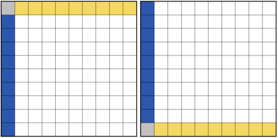
One major change in AGSL compared to traditional GLSL is the coordinate space, In GLSL, the fragment coordinate (fragCoord) is relative to the lower left. AGSL matches the screen coordinate system of Canvas, which means that the Y axis begins from the upper left corner.
Once you tackle the hurdle that is coordinates, it's time for Color Spaces.
GLSL is typically designed for common platforms, assuming standard RGB and non-premultiplied colors. However, in Android, the color space of a Canvas determines the working color space for drawing. Source content, such as shaders (including BitmapShader), also has color spaces to help with this AGSL comes with these intrinsic functions:
half3 toLinearSrgb(half3 color)
half3 fromLinearSrgb(half3 color)
These convert colors between the working color space and Android's LINEAR_EXTENDED_SRGB color space. That space uses the sRGB color primaries (gamut), and a linear transfer function. It represents values outside of the sRGB gamut using extended range values (below 0.0 and above 1.0).
And since AGSL doesn't know if the uniform contains colors it won't automatically apply a color conversion to them. You can label half4 / float4 / vec4 with layout(color), which lets Android know that the uniform will be used as a color, allowing it to transform the uniform value to the working color space.
When Should You Not?
Now that you understand how shaders work, you might be wondering when and why you shouldn’t use them—or more importantly, when you should. To answer that, it helps to understand what shaders can do that tools like Lottie or Rive cannot. Unlike Lottie or Rive, which are primarily vector-based animation tools, shaders operate at the pixel level. This allows for a level of customization and dynamic visual effects that go far beyond traditional animation frameworks.
For example, in the snippet below by Rebecca, a noise pattern shader is applied directly to the layout, creating an effect that simply isn’t achievable using Lottie or Rive. Shaders give you the power to manipulate every pixel of your content, opening up a whole new realm of visual possibilities.
But you might ask that this is a very niche example and that you don't need to visually modify the layout or UI components everyday, and that's exactly the point. Shaders only make sense when you want your UI/animation to be interactive.
Your Translator
To avoid an exhaustive comparison, this section highlights the most significant differences between GLSL and AGSL. If you want a detailed GLSL to AGSL checkout docs here, for deep diving into GLSL language checkout here.
Color Functions
The below color functions help us tackle the above discussed color space issues
Program Functions
Vector Functions
Composing Pixels
This is the part everyone is probably is waiting for – we will finally convert a GLSL/SKSL shader to run on AGSL.
This is an sample from the Skia playground. We will try to achieve the same output in Android using AGSL. Let's go line by line with some code explanation
A few key points to remember before we code AGSL:
We pass in variables using uniform, and then we pass those values to the shader at runtime using setXUniform() method. In the following code conversion, we will follow the same naming conventions as the SKSL playground.
uniform float3 iResolution;      // Viewport resolution (pixels)
uniform float  iTime;            // Shader playback time (s)
uniform float4 iMouse;           // Mouse drag pos=.xy Click pos=.zw (pixels)
uniform float3 iImageResolution; // iImage1 resolution (pixels)
uniform shader iImage1;          // An input image.
So let's start!
Line 1
SKSL
vec4 main(vec2 FC) {vec4 creates a 4D vector that can be used for rendering color, FC stands for Frag Coordinates. FC provides the current coordinates of where the shader is running, but what does that even mean? As we know, shader/gpu code run on pixels of the provided space and shader languages only run the main function on every pixel, thus giving us information of the current pixel. How can it be useful? Let's say you have a filled red circle drawn on the screen, and you want to figure out if you're currently inside the red circle. If you have per-pixel information, you can simply run an if condition to check if the current pixel is red or not.
AGSL
half4 main(in float2 fragCoord) {vec4 becomes half4 and vec2 becomes float4. Now you might wonder why vec2 becomes float2, when vec4 becomes half4? Since our shader code is meant to run on mobile devices with a vast range of screen resolutions and dimensions having a program run on high precision doesnt make sense, and thus AGSL has precision vectors. half being as the name suggests, is half of a full float, i.e. only 16-bit. Using half4 helps manage memory efficiently.
Line 2
SKSL
vec4 o = vec4(0);with vec4 we are creating an output pixel. vec4(0) is similar to writing vec4(0,0,0,0) and creating a black pixel.
AGSL
half4 o = half4(0);Line 3
SKSL
vec2 p = vec2(0), c=p, u=FC.xy*2.-iResolution.xy;Like C or C++, we can create a variable of the same type in the same line, reducing lines of code, so let's break it down one by one.
vec2 p = vec2(0) creates a 2d vector containing xy values. p can be considered a positional vector. c=p creates c as a copy of the positional vector, essentially allowing us to modify the pixel at the positional vector (will try to make sense of it as we code :|). u=FC.xy*2.-iResolution.xy; in the first part FC.xy*2. changes (0,0) to (2*width - 2, 2*height - 2), and finally subtracting iResolution.xy; which are your screen coords, roughly centers the coordinates.
AGSL
float2 p = float2(0), c = p u = fragCoord.xy * 2.0 - iResolution.xy;
The logic remains the same. One thing to note is that SKSL uses 2., while the AGSL equivalent uses 2.0. In shader languages, writing 2.0 as 2. is valid—the missing digit after the decimal is interpreted as 0.
Line 4
SKSL & AGSL
float a;float a- Declares a single-precision floating-point variablea. This variable will be used within the loop.
Line 5
SKSL & AGSL
for (float i=0; i<4e2; i++) {- This line creates for loop that itrates for
4e2which is equivalent to4*10^2or 400.
Line 6
SKSL & AGSL
a = i/2e2-1.;- This line is responsible for creating layers in the circle it iterates
2*10^2.
Line 7
SKSL
p = cos(i*2.4+iTime+vec2(0,11))*sqrt(1.-a*a);p = cos(i*2.4+iTime+vec2(0,11))*sqrt(1.-a*a);- This line calculates the value of the 2D vectorp. This is very important as it is responsible for the shape/pattern generation.cos(...)- Calculates the cosine of each component of the resulting 2D vector. The cosine function outputs values between -1 and 1.i*2.4- Multiplies the loop counter by2.4. This changes the frequency of the cosine function based on the iteration.iTime- determines the speed of the animation.1.-a*a- Calculates1−a^2. Sincearanges from roughly -1 to 1,a^2ranges from 0 to 1. So,1−a^2ranges from 0 to 1.sqrt(1.- a*a);- It ensures that asagoes from -1 to 1 (or vice-versa), this term goes from 0 to 1 and back to 0, essentially managing the pattern which is generated.cos(...) * sqrt(...)- is the important part of the logic, the calculation produces Lissajous-like curve or spiral, constrained by thesqrtterm, and animated by overtime to generate a spear like shape.
AGSL
p = cos(i * 2.4 + iTime + float2(x,y)) * sqrt(1.0 - a * a);as it is the core of the program, the logic remains the same and vec2 gets converted to float2.
Line 8
SKSL
c = u/iResolution.y+vec2(p.x,a)/(p.y+2.);uis normalised 2d vector that is responsible to center the placement.- The
ucoordinates is scaled and dividing both components ofubyiResolution.y(the height of the viewport) normalizes the coordinates with respect to height, making them aspect-ratio dependent.
AGSL
c = u / iResolution.y + float2(p.x, a) / (p.y + 2.);
Line 9
SKSL
o += (cos(i+vec4(0,2,4,0))+1.)/dot(c,c)*(1.-p.y)/3e4;This is the final piece of the puzzle, o is the final output pixel that's being rendered.
o +=- Adds the calculated small color contribution to the accumulatoro.cos(...)- cos as we know calculates and outputs a value from-1to1.i+vec4(0,2,4,0)- Creates a 4D color vector by addingito each component ofvec4(0.0, 2.0, 4.0, 0.0)vec4(R,G,B,A) . So it becomesvec4(i, i+2.0, i+4.0, i).cos(...)+1- Adds 1 to each component, shifting the range to 0 to 2. This is a common way to make cosine values suitable for color intensities (avoiding negative values).(cos(...)+1.)/dot(c,c)- Divides the 4-component color vector by the scalardot(c,c). This means pixels wherecis close to the origin will get brighter colors, creating a spotlight or glowing effect around wherecmaps to(0,0).*(1.-p.y)- Multiplies the color contribution by this(1.-p.y)factor, further modulating the brightness./3e4- Divides the entire contribution by3×10^4=30000. This is a scaling factor to keep the accumulated color values in a reasonable range (typically 0-1) over 400 iterations.
AGSL
o += (cos(i + half4(0,2,4,0)) + 1.) / dot(c,c) * (1. - p.y) / 3e4;Final AGSL Code
uniform float2 iResolution;
uniform float iTime;

half4 main(in float2 fragCoord) {
  half4 o = half4(0);
  float2 p = float2(0), c = p;
  float2 u = fragCoord.xy * 2.0 - iResolution.xy;

  float a;

  for (float i=0; i<4e2; i++) {
    a = i/2e2-1.;
    p = cos(i * 2.4 + iTime + float2(0,11)) * sqrt(1.- a * a);
    c = u / iResolution.y + float2(p.x, a) / (p.y + size);
    o += (cos(i + half4(0,2,4,0)) + 1.) / dot(c,c) * (1.0 - p.y) / 3e4;
  }

  return o;
}
Conclusion
I hope this blog was helpful to you and helped you understand at least a little bit about how shaders work. The sample that we translated works, but is not the best optimized, and so if you want to dip your toes into shaders even further, I'd highly recommend you to try optimizing it!
Happy Composing 💚💚💚
Bonus Links
- Animation Talk App built using native animations and shaders
 MadFlasheroo7